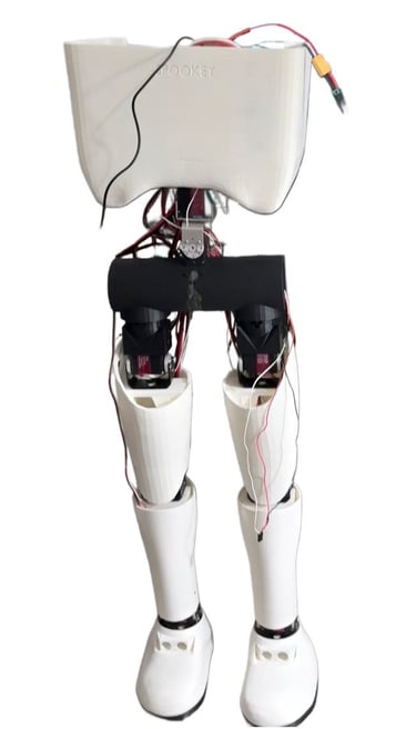
CAD Overview
All of the mechanical parts of the robot are custom-designed and 3D printed in-house. I use a Creality K1 SE to manufacture almost every structural component in PLA, except for the shoe sole, which is printed in TPU. TPU works better for the sole because it provides flexibility, grip, and shock absorption, which helps when the robot is walking on smooth or slippery surfaces.
The overall mechanical design focuses on simplicity, reliability, and working within a realistic budget, while still allowing the robot to balance and walk in a controlled way.
Leg Structure and Degrees of Freedom
Each leg is designed with a straightforward joint layout to keep the system manageable.
The knee has one degree of freedom, and the ankle also has one degree of freedom. This was a deliberate choice to keep the design simple and reduce mechanical and control complexity.
The hip has two degrees of freedom:
Pitch, which allows the leg to move forward and backward
Yaw, which allows the leg to rotate about its own vertical axis
To prevent any unwanted roll movement (side-to-side tilt) at the hip, I placed a bearing between the two hip servos. A rod passes through the arm of the top servo and connects to the bottom (pitch) servo. This rod goes through the bearing, so the two servos work together cleanly, almost like puzzle pieces, while keeping the joint mechanically stable.
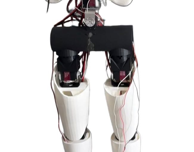
Torso Balancing System
The robot uses two high-torque 150 kg·cm servo motors for the torso, stacked vertically.
These two motors handle:
Roll (side-to-side movement)
Pitch (front-to-back movement)
The main purpose of this system is balance. Since the ankles do not have multiple degrees of freedom, balance corrections that would normally happen at the ankle are instead handled by the torso. This allows the robot to shift its weight dynamically while walking.
Actuator Choices and Design Constraints
The design is not the most industrial or research-grade system out there, and that’s intentional.
High-end actuators can easily cost $500 per motor, and while building custom actuators is possible, it adds significant complexity. Stepper motors were also considered, but they come with their own trade-offs in size, control, and cost.
Given the budget and goals of this project, servo motors offered the best balance between torque, cost, simplicity, and availability. For this robot, servos are more than capable of doing the job effectively.
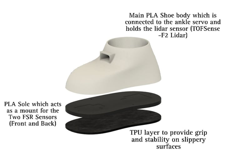
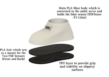
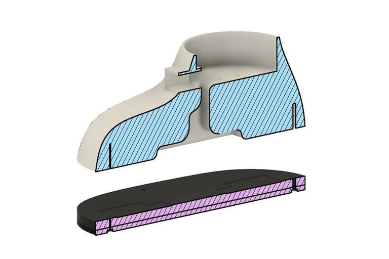
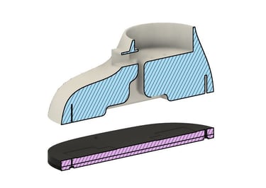
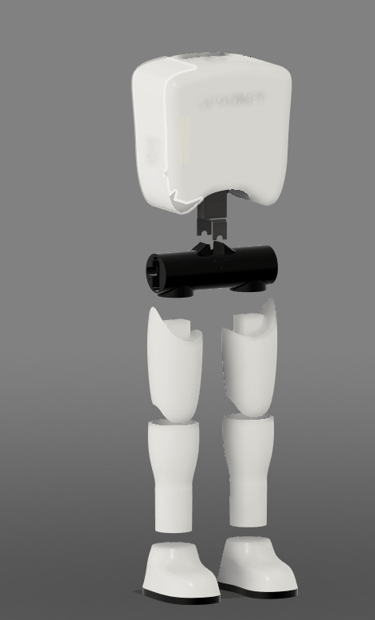
Shoe Assembly and Ground Interaction
Each shoe is made up of three main layers:
Top Layer (Main Shoe Body)
This makes up about 90% of the shoe structure. It houses a LiDAR sensor at the front for obstacle detection. The electrical details of this sensor are covered in the electrical section.Middle Layer (Sensor Layer)
This layer includes a dedicated slot for FSR pressure sensors, which are used to detect ground contact and weight distribution. These sensors are also explained further in the electrical section.Bottom Layer (TPU Sole)
The bottommost layer is a 4 mm thick TPU sole, designed to provide grip, durability, and stability while walking, even on slippery surfaces.
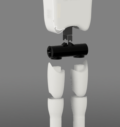
Pelvis and Core Structure
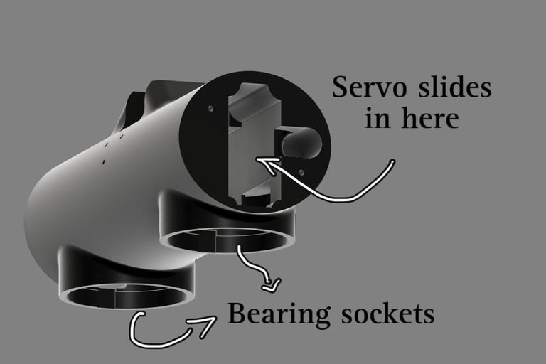
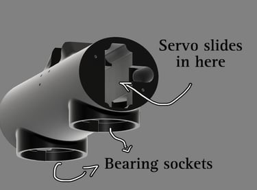
The pelvis, which is the black cylindrical component, acts as the base of the leg system.
Inside the pelvis:
Two yaw servos are mounted, one for each leg
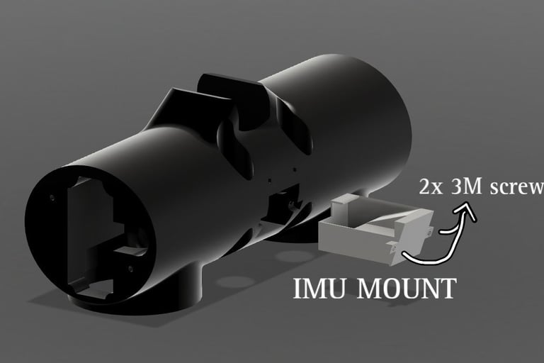
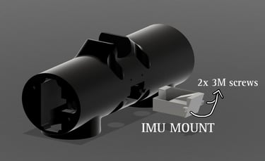
An IMU is installed for orientation and balance feedback
The two 150 kg·cm torso servos are stacked on top of the pelvis and partially housed within it
This design allows the pelvis to act as a structural hub, cleanly connecting the legs, torso, and balance system into a single compact unit.
Four 80 kg·cm torque servo motors: one dedicated to the knee and one to the ankle, with two additional servos at the hip joint providing pitch and roll rotation.
Two FSR pressure sensors integrated into the sole. Among its functions, it detects whether the leg is in contact with the ground, serving as a boolean check before the opposite leg is lifted.
One TOFSense-F2 Lidar Sensor mounted near the ankle to detect nearby obstacles at ground level.
Each leg consists of the following components:
Contact
swayamrathod@sway.bet
(404) 910-6857